Manual Input Visio
Accessibility:
- Vizio Manual Input
- Manual Input Visio Free
- Manual Input Visio Software
- Manual Input Visio Example
- Manual Input Visio Tutorial
VIZIO VW42L FHDTV10A User Manual. Television Antenna Connection Protection. External Television Antenna Grounding. If an outside antenna/satellite dish or cable system is to be connected to the TV, make sure that the antenna or cable system is electrically grounded to provide some protection against voltage surges and static charges. To purchase or inquire about accessories and installation services for your VIZIO product, visit our website at. Or call toll free at (877) 698-4946. We recommend that you register your VIZIO product at. WHEN READING THIS MANUAL IMPORTANT SAFETY INSTRUCTIONS. Read these instructions.
Contact VIZIO for accessibility support at:
Email:[email protected]
Phone: 1-877-698-4746
IMPORTANT SAFETY INSTRUCTIONS:

Your Unit is designed and manufactured to operate within defined design limits, and misuse may result in electric shock or fire. To prevent your Unit from being damaged, the following rules should be observed for its installation, use, and maintenance. Please read the following safety instructions before operating your Unit. Keep these instructions in a safe place for future reference.

- Heed all warnings.
- Follow all instructions.
- Do not use this Unit near water.
- Clean only with a dry cloth.
- Do not block any ventilation openings. Install in accordance with the manufacturer’s instructions.
- Do not install near any heat sources such as radiators, heat registers, stoves, or other Unit (including amplifiers) that produce heat.
- Do not defeat the safety purpose of the polarized or grounding-type plug. A polarized plug has two blades with one wider than the other. A grounding type plug has two blades and a third grounding prong. The wide blade or the third prong are provided for your safety. If the provided plug does not fit into your outlet, consult an electrician for replacement of the obsolete outlet.
- Protect the power cord from being walked on or pinched particularly at the ends where the plug is located, near convenience receptacles, or where they exit from the Unit.
- Only use attachments/accessories specified by the manufacturer.
- Use only with the stand, tripod, or bracket specified by the manufacturer, or sold with the Unit. When a cart is used, use caution when moving the cart/Unit combination to avoid injury from tip-over.
- Unplug this Unit during lightning storms or when unused for long periods of time.
- Refer all servicing to qualified service personnel. Servicing is required when the Unit has been damaged in any way, such as when the power supply cord or plug is damaged, liquid has been spilled or objects have fallen into the Unit, the Unit has been exposed to rain or moisture, does not operate normally, or has been dropped.
- To reduce the risk of electric shock or component damage, switch off the power before connecting other components to your Unit.
- Unplug the power cord before cleaning your Unit. A damp cloth is sufficient for cleaning. Do not use a liquid or a spray cleaner on your Unit. Do not use abrasive cleaners.
Package Contents:
- VIZIO Sound Bar
- Remote Control with 2x AAA Batteries
- Power Cable
- Stereo RCA to 3.5mm Audio Cable
- 3.5mm to 3.5mm Audio Cable
- Digital Optical Cable
- 2x Wall Mount Brackets (Sound Bar)
- Wall Mount Template
- 2 x Wall
- Mount Screws
- User Manual
- Quick Setup Steps
Controls & Connections:
Back of Sound Bar:
Controls & Connections:
First-time Setup:
- Choose the best possible connection cable type and connect it to your TV.
- Connect the power cable to the sound bar AC IN as shown. Plug the power cable into an electrical outlet.
- Remove the battery cover by gently sliding it away from the remote.
- Insert the included batteries and gently slide the battery cover back into place.
- After turning on both your TV and sound bar, it will automatically begin searching for an active input.* The LED indicator on the front of the sound bar will begin cycling in different colors through inputs until an audio source is detected.
Using the Remote:
Vizio Manual Input
Proper Placement:
For the best sound experience, position the sound bar as shown. The sound bar should be close to ear level.
Mode & Level Settings:
The LED indicators will behave differently with each function
Mode & Level Settings:

Using Button Combinations:
There are other functions that are triggered by different button combinations on the sound bar.
Bluetooth Pairing:
- Press and hold the Bluetooth button ‘B’ on the sound bar or remote control for three (3) seconds.
- Search for the sound bar (VIZIO SB3620n) using your Bluetooth device. For more information, refer to the user documentation that came with the device.
- Now you can play audio from your Bluetooth device. Volume can be controlled on both your source device and the sound bar.
Using Bluetooth Mode:
- Your sound bar supports music streaming from devices with Bluetooth capability. (Device compatibility will vary, see your device’s documentation for more information.)
- Once you have paired your source device to the sound bar your device should remain paired (within range).
- If the source is changed back to Bluetooth, any paired Bluetooth device will reconnect automatically.
- If the input is changed, the Bluetooth device will disconnect.
Advanced Setup:
Specifications:
Manual Input Visio Free
Note: To read the complete user manual, please download the following file:
We normally use visio to build documents which helps developer to understand the flow of the modules and projects. These are common used shapes that’s why I am just taking the definition from Microsoft itself so it would be consistent for everyone.
Its just a copy paste from Microsoft visio but the main concept behind is to share
What the flowchart shapes represent

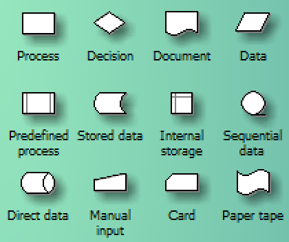
When you open the Basic Flowchart template, the Basic Flowchart Shapes stencil opens too. Each shape on the stencil represents a different step in a process.
Manual Input Visio Software
Of all of the shapes on the Basic Flowchart Shapes stencil, only a few are commonly used. Those commonly used shapes are described here.
- Terminator Use this shape for the first and last step of your process.
- Process This shape represents a step in your process.
- Predefined process Use this shape for a set of steps that combine to create a sub-process that is defined elsewhere, often on another page of the same drawing.
- Decision This shape indicates a point where the outcome of a decision dictates the next step. There can be multiple outcomes, but often there are just two —yes and no.
Document This shape represents a step that results in a document. - Data This shape indicates that information is coming into the process from outside, or leaving the process. This shape can also be used to represent materials and is sometimes called an Input/Output shape.
- Flowchart shapes You can right-click this multi-shape to set to any of the following shapes: Process, Decision, Document, or Data. Any text you type onto the shape, or information you add to its Shape Data, remains with the shape.This is what the shape looks like on the stencil:This is what you see when you drag the shape onto the drawing page and right-click it:
- Stored data Use this shape for a step that results in information being stored.
- On-page reference This small circle indicates that the next (or previous) step is somewhere else on the drawing. This is particularly useful for large flowcharts where you would otherwise have to use a long connector, which can be hard to follow.
- Off-page reference When you drop this shape onto your drawing page, a dialog box opens where you can create a set of hyperlinks between two pages of a flowchart or between a sub-process shape and a separate flowchart page that shows the steps in that sub-process.
Manual Input Visio Example
Less frequently used flowchart shapes
Manual Input Visio Tutorial
- Dynamic connector This connector draws a path around shapes it encounters.
- Line-curve connector This connector has adjustable curvature.
- Auto-height box This is a bordered text box that adjusts to accommodate the amount of text you type. You can set the width by dragging the sides of the shape. Although this shape doesn’t represent a step in a process, it is a handy way to add a text box to your flowchart.
- Annotation This bracketed text box adjusts to accommodate the amount of text you type. You can set the width by dragging the sides of the shape. Like the Auto-height box shape, this shape doesn’t represent a step in a process. Use this to add comments about your flowchart shapes.
- Manual input This is a step where a person provides information to the process.
- Manual operation This is a step that must be performed by a person.
- Internal storage This shape represents information stored on a computer.
- Direct data This shape represents information stored so that any single record can be accessed directly. This represents how a computer hard-drive stores data.
- Sequential data This shape represents information stored in sequence, such ad data on a magnetic tape. When data is stored in sequence, it must be retrieved in sequence. For example, in order to access record 7 you would have to first go through records 1 through 6.
- Card and Paper tape This shape represents a physical card or paper tape. Early computer systems used a system of punch cards and paper tape to store and retrieve data and to store and run programs.
- Display This shape represents information that is displayed to a person, usually on a computer screen.
- Preparation This shape indicates where variables are initialized in preparation for a procedure.
- Parallel mode This shape shows where two different processes can operate simultaneously.
- Loop limit This shape marks the maximum number of times a loop can run before it must go on to the next step.
- Control transfer This shape indicates a step that goes to a step other than the typical next step when certain conditions are met.

Please visit my official blog for future.